VSWR Testing: Free Space Chamber Validation (up to 100 GHz)
Don’t settle for testing that adds complexity and risk to your schedule. Shielding Integrity Services (SIS) delivers expert, fully accredited, independent VSWR Testing based on decades of practical, hands-on experience—not just theory. We use state-of-the-art automated systems that maximize testing efficiency, ensuring fast turnaround of accurate data and quick troubleshooting for any required performance adjustments. Whether validating a compact 3-meter setup or a specialized 10-meter facility anywhere in the world, SIS delivers the precise, compliant results you need to confidently move your projects forward.
Test Objectives & Technical Necessity
The VSWR Free Space test is designed to detect and measure reflected radio waves indirectly entering the chamber’s quiet zone from the source antenna. This is a highly stringent test used to verify specified chamber performance and detect absorber design limitations.
Technical Specifications
SIS has conducted this type of anechoic performance measurement at numerous facilities worldwide, validating performance across wide, critical frequency bands.
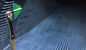
- Frequency Range: Standard capabilities include measurements from 500 MHz through 100 GHz.
- Test Goal: Verification of chamber performance where traditional free-space methods are not practical.
Methodology & Data Integrity
We leverage advanced, proprietary equipment and software to ensure maximum data accuracy and repeatability for measurements.
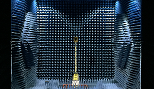
Automated Measurement System
- Our quiet zone measurement systems consist of a positioning system that traverses the quiet zone in longitudinal and transverse directions while the probe antenna’s azimuth angle is indexed (clocked) at a specified step size (typically 10° or 15°).
- Our proprietary software automatically captures a repeatable series of RF reflectivity measurements. The probe angles are typically collected automatically in a sequence of measurements that covers a range of angles, depending on the traverse direction.
- The data is captured using a spectrum analyzer and stored on a portable computer for processing and analysis using proprietary software.
Standards & Performance Validation
This measurement verifies compliance with the industry’s most trusted international standards for anechoic performance, giving you confidence in your data.
- Primary Standard: The standard method for measuring anechoic performance is described in IEEE Standard 149-2021.